Masonry walls, especially those that contribute to historic building enclosures and structural systems, often require stabilization as part of a rehabilitation project. For historic buildings, the desire to retain and preserve the existing building fabric with minimal impact rather than large-scale removal and replacement is generally preferred. This blog will address evaluation techniques, general repair design, construction quality control techniques, commercially available mechanical ties/anchoring, and compatible grouting.

Project Implications/Implementation Benefits
In-place masonry stabilization allows for historic masonry and assemblies to remain, preserving the original materials, construction configurations, and architectural intent. There is inherent value in allowing building facades and ornamentation to influence visitors in the same fashion they did hundreds of years ago. While the up-front design cost for masonry stabilization may be greater than the cost for traditional masonry design, the overall construction cost of stabilization is often less than rebuilding entire masonry structures and facades. Thus, the benefit of masonry stabilization is threefold:
- The owner achieves a stabilized facility
- The project typically experiences cost and schedule savings over rebuilding
- The building retains its intrinsic architectural value
Stabilization Measures
Various options for the stabilization of existing masonry structures are available. Helical ties, injection grouting, stay-in-place anchors, and combinations of these methods can be tailored to suit individual projects based on the extent of stabilization required.
Helical Ties
Helical ties are lengths of twisted stainless steel installed either perpendicular or parallel to masonry assemblies. Helical ties can be used for a multitude of stabilization applications, including securing multiple wythes of masonry together, stitching cracks, and pinning lintels and arches. Helical ties can be installed with or without grout, contingent on the required strength and the installation orientation. Strength requirements vary, depending on the building loads, back-up material, and available embedment. Due to a wide range of embedment conditions, pull-out testing is required during both the design and construction phases of a project to verify allowable and achieved values. Helical ties can be designed using ACI 530 (Building Code Requirements for Masonry Structures), Section 12.2.2 in conjunction with available load tables from manufacturers and field testing. Prescriptive requirements for anchored masonry veneer can also be found in the same section. It is important to note that ACI 530 lists requirements for an anchored veneer system, not specific requirements for helical tie repairs. In many cases, designs err on the conservative side to allow for variability in substrate conditions.’Helical ties are lengths of twisted stainless steel installed either perpendicular or parallel to masonry assemblies. Helical ties can be used for a multitude of stabilization applications, including securing multiple wythes of masonry together, stitching cracks, and pinning lintels and arches. Helical ties can be installed with or without grout, contingent on the required strength and the installation orientation. Strength requirements vary, depending on the building loads, back-up material, and available embedment. Due to a wide range of embedment conditions, pull-out testing is required during both the design and construction phases of a project to verify allowable and achieved values. Helical ties can be designed using ACI 530 (Building Code Requirements for Masonry Structures), Section 12.2.2 in conjunction with available load tables from manufacturers and field testing. Prescriptive requirements for anchored masonry veneer can also be found in the same section. It is important to note that ACI 530 lists requirements for an anchored veneer system, not specific requirements for helical tie repairs. In many cases, designs err on the conservative side to allow for variability in substrate conditions.
Injection Grouting
Injection grouting is typically used to fill existing voids in masonry assemblies to provide a stronger composite system and to bond the wythes together. Through injection, grout is either gravity-fed or pumped under low pressure (note – high pressure injection methods may damage the wall construction) into masonry cavities to flow into voids within a wall assembly. During the evaluation phase, the location and extent of voids can be better defined through destructive field testing (test cuts) or non-destructive testing such as surface penetrating radar (SPR) or impact echo testing.. The type of grout can then be designed based on application, void sizes, and compatibility with existing mortar and masonry. For historic renovations, the existing historic mortar should be tested using petrographic analysis (per ASTM C1324) to improve the effectiveness of the rehabilitation design. The mortar may also be governed by ASTM C1713 Standard Specification for Mortars for the Repair of Historic Masonry. Grouts associated with injection grouting typically have high vapor permeability and low shrinkage and are flowable and self-consolidating. In the case of historic structures, the grout is often pozzolanic lime based, but will vary by application. Before grouting, the areas to receive grout are flushed clean to remove excess debris and are wetted to provide an adequate substrate condition for the flowing grout. The grout is then injected in lifts determined by the design team, often under the supervision of a special inspector, who will submit grout injection records and mortar test results to the design team.

Stay-in-Place Anchors
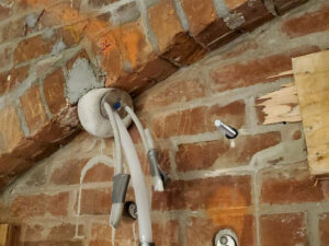
Stay-in-place anchors can consist of custom anchor rods grouted in place to provide additional strength to the masonry assemblies. Many stay-in-place anchors are used in conjunction with injection grouting to provide a stabilization repair. The rods (typically stainless steel) should be designed to provide sufficient strength and development per ACI 530. A specialty anchor, known as a port anchor, combines stay-in-place anchors with injection grouting. These proprietary systems integrate stainless steel rods with tubes connected to expanding sock anchors. Water is pumped through the tubes to flush and wet the cavities, followed by the grout pumped under a low pressure to secure the anchors and rods in place. These anchors can pin wythes of masonry together and combine the benefits of stay-in-place anchors and injection grouting. To improve the stabilization system, port anchors can be used in conjunction with other strengthening methods to provide a composite repair.
Case Studies
1871 Masonry and Stone Arch Stabilization
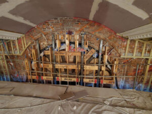
An existing masonry wall surrounding a 19th-century sandstone tracery and stained glass rose window, measuring sixteen feet in diameter, needed to be revitalized at this historic building. Portions of the stone tracery were deteriorated and required partial replacement. Following the forensic evaluation and test cuts, it was determined that the stone tracery carried vertical and lateral loads. Stabilization of the brick masonry wall arch above the tracery would be required to allow for the individual stone replacement of the window during construction. The design team determined that the existing masonry could be strengthened by a combination of anchors and grouting. Structural improvements to the multi-wythe brick wall would create an arch, allowing repair work to be performed below. Since historic preservation was a must for this building, the design team developed a support methodology including injection grouting, port anchors, and grouted-in-place anchors. The multi-wythe brick wall was deep repointed, tied together with helical ties, stabilized with injection anchors, and consolidated with injection grout. Stainless steel anchor rods were inserted radially at the rose window head to tie the masonry wythes together, with some rods measuring over seven feet long. This multi-faceted approach provided increased strength to the overall masonry wall and window assembly.

1895 Stone Turret Stabilization
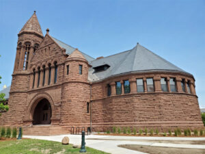
One of the building’s stone turrets had been experiencing water infiltration since shortly after the building was constructed in 1895. This led to the deterioration of the existing mortar, as well as the loosening of the brownstone facing, which was installed over a redstone rubble and brick back-up. Destructive test cuts revealed deteriorated mortar collar joint between the brownstone face and the red stone backup. Some areas of brownstone facing were destabilized and required rebuilding rather than in-place stabilization. SPR scanning was utilized to reveal larger voids that required consolidation prior to the grouting work. The design included a deep mortar joint repointing, helical tie installation to mechanically secure the brownstone and back-up, and low-pressure injection grouting.
Summary
The processes mentioned above can be replicated in other historic masonry projects to provide effective stabilization and rehabilitation for the building owner. Each specific case will have its own nuances, including existing conditions, structural loading, budget, and schedule. The combination of effective masonry stabilization design and willingness to preserve architectural heritage will provide a beautiful end result.
Tagged In:
Building Enclosure Design & Consulting
