Natatoriums are notoriously difficult facilities to design and construct as there are many important factors to consider that, if overlooked, can result in premature failure of the building systems and/or hazardous conditions for building occupants. With respect to the building enclosure, important design and installation practices will help provide properly performing and functioning assemblies. Several important considerations include:
- Providing a continuous, properly installed roof vapor retarder that connects and seals to the air barriers in the wall assemblies.
- Designing for, and installing continuous insulation in multiple layers to reduce the potential for condensation
- Limiting thermal bridging that typically occurs from structural components or fasteners within the systems
- Limiting penetrations through the enclosure and/or providing proper flashing details when penetrations cannot be avoided
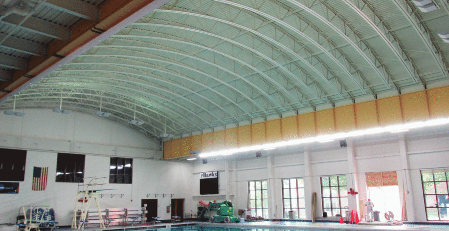
When these design considerations are disregarded, it can result in premature failure of the enclosure assemblies, as evidenced at a recent natatorium project in Montgomery County, MD. The facility, which was constructed in the early 1990s, is divided into five separate and distinct areas, two of which house indoor swimming areas. The roof assembly over the swimming areas was constructed as follows (from top to bottom):
- 24-gauge standing seam, pre-painted galvanized steel roof panels
- 30 lb. roof felt, fastened to the composite insulation board
- Composite insulation board (7/16” OSB factory-laminated to 2-1/2” polyisocyanurate insulation)
- Vapor retarder/barrier
- 1-1/4 exterior plywood sheathing
- Steel deck

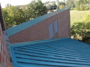
These two roof areas experienced severe degradation of the metal roof panels with surface rust noted throughout and large areas of panel corrosion with exposed felt underlayment. The level of corrosion observed in the metal roof panels +/-25 years after construction was unusual and indicated there may be issues with the vapor barrier. The original construction documents followed basic natatorium design principles, which detailed the vapor barrier extending vertically onto rising walls and curbs, following destructive testing, and connecting to the wall air barrier at transitions. However, following destructive testing, it does not appear that these requirements were implemented during construction.

To reduce the possibility of moisture migration into the new roof system, the new vapor barrier was designed to be installed over the existing roof that encapsulated the wood blocking at the ridges, rakes, and eaves and tied into existing curbs and the exterior wall brick masonry. The insulation thickness was increased and installed in multiple layers to meet current code requirements: 30 lb. roof felt was specified under the new standing seam metal roof panels.

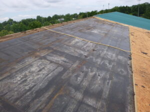
During demolition of the existing roof assembly, it was observed that the existing vapor barrier was not continuous at edge transitions, penetrations, or at eight large skylight curb assemblies. The vapor barrier terminated approximately 1/4” short of all rising walls and curbs, providing a path for moisture migration from the interior. Although we could not visually verify if the roof vapor barrier connected the wall air barrier at the ridges, rakes, and eaves, evidence of moisture staining on the existing vapor barrier and degradation of the insulation at these edge conditions indicated these connections were incomplete.
Consistent migration of chemical- and moisture-laden air from the building’s interior due to an improperly flashed vapor barrier was likely a significant contributing factor for the premature failure of the roof assembly. This project serves as an example of the importance of designing and installing a complete vapor to air barrier assembly.
Tagged In:
Building Enclosure Design & Consulting
